LCR Meters
Sciospec’s LCR meters deliver high-performance measurement solutions tailored to both research and industrial applications. Built on our proven impedance measurement technology, the LCR-1 and LCR-3 combine accuracy, speed, and flexibility. Whether you need a compact benchtop device or a scalable system for automated testing, our LCR meter solutions are engineered to meet the demands of modern component analysis.
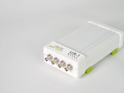
🔎 Looking for a precision in a compact form Discover the LCR-1
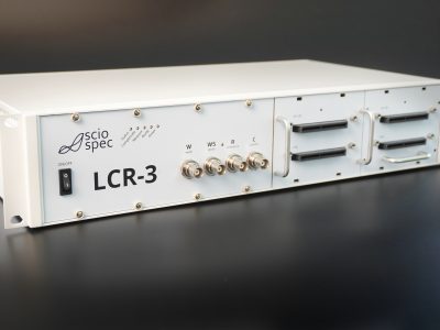
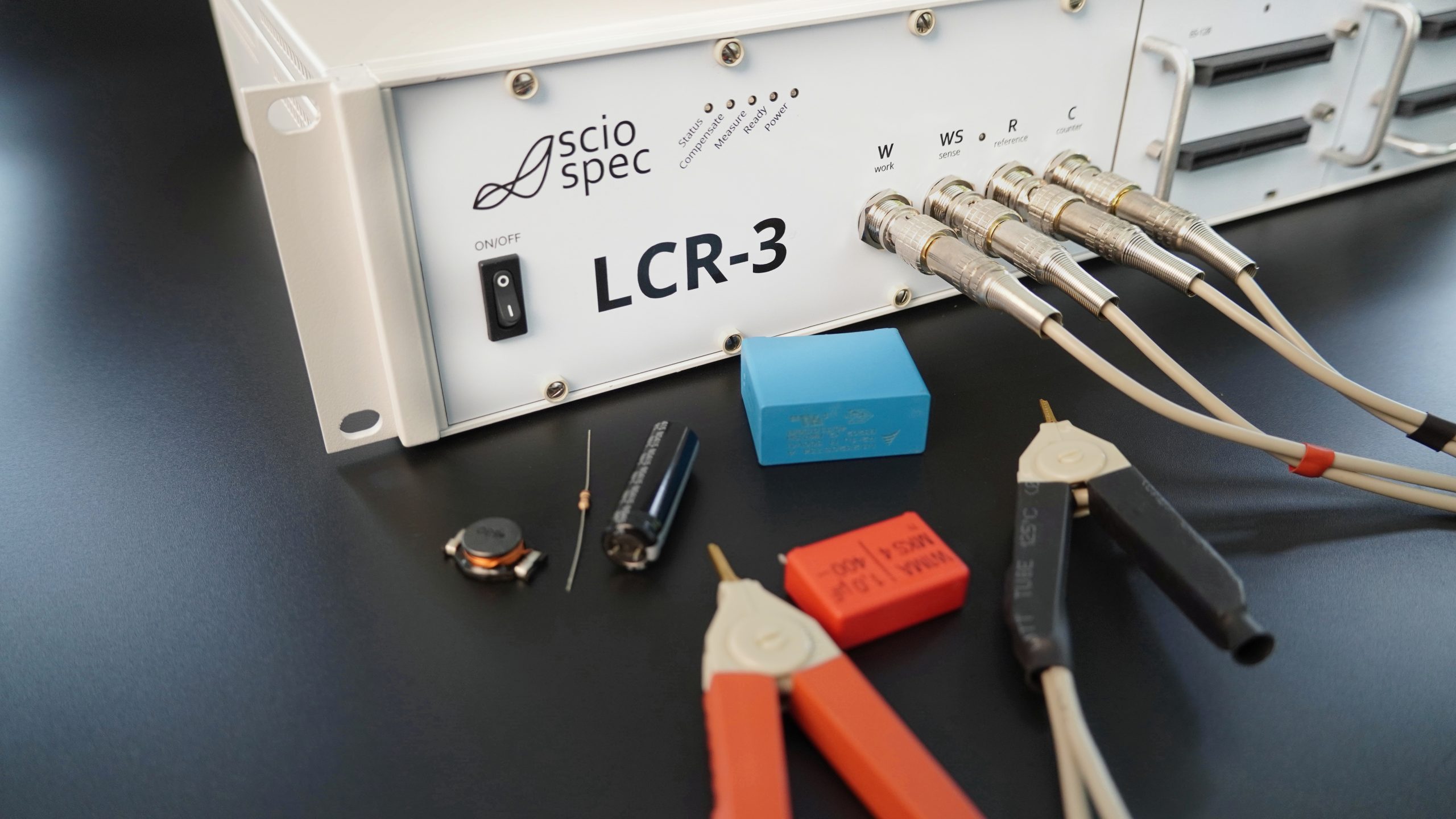
⚙️ Need a solution for component testing? Explore the LCR-3

What is a Precision LCR Meter and how does it work?
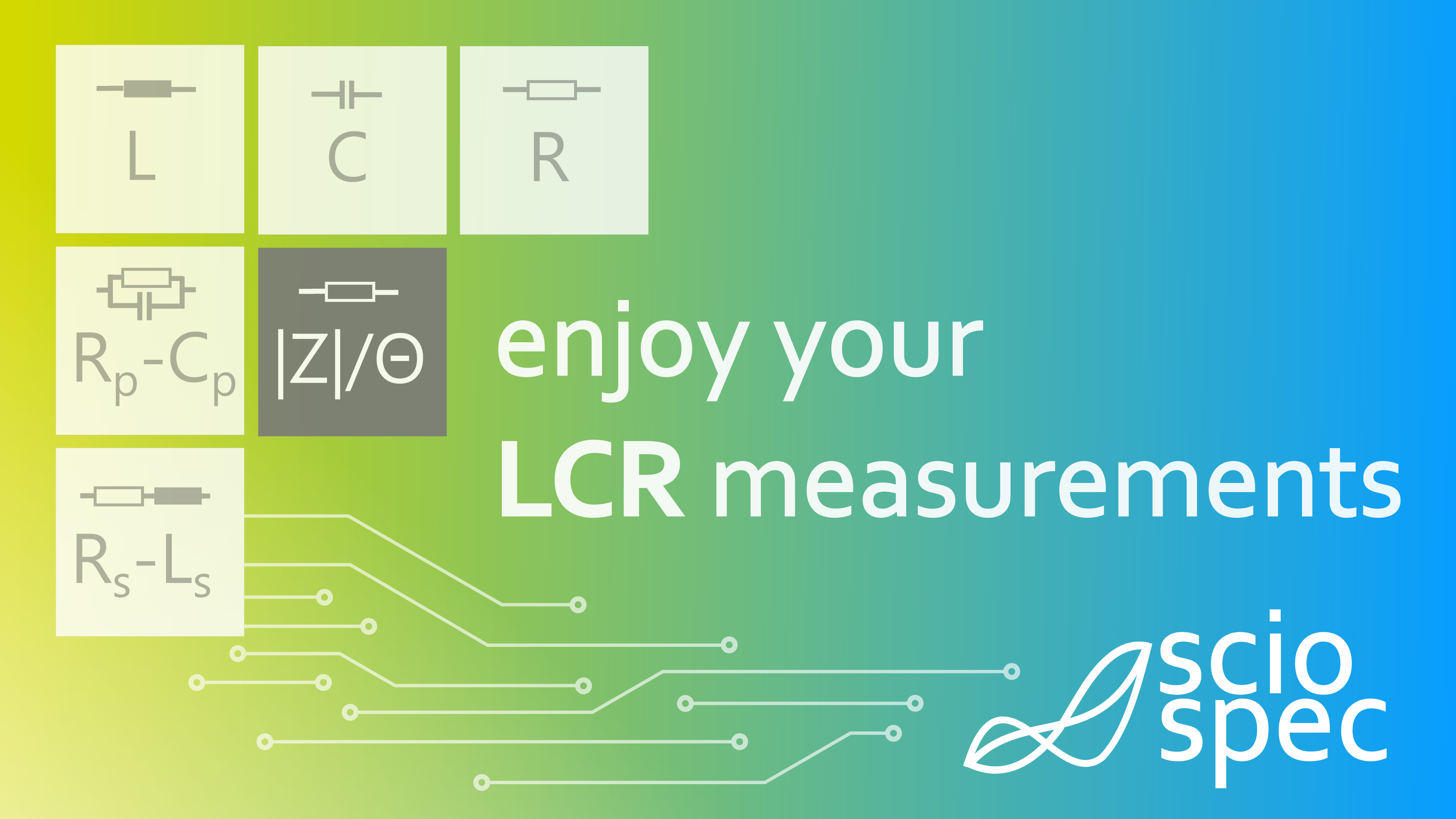
The LCR meter is a specialized electronic test instrument used to measure electrical properties, specifically the inductance (L), capacitance (C), and resistance (R) of electronic components or other objects. The name “LCR” reflects the three basic types of passive electronic components that the meter is designed to analyze. Typical measurements determine not only a single L, C or R component, but combinations thereof, for example simple series or parallel circuits of RC or LC combinations.
More advanced instruments can characterize complex DUT configurations and therefore support multi-frequency measurement modes, similar to the operating principle of impedance analyzers.
This instrument class is widely used in electronics manufacturing, research and development, quality control, and troubleshooting. They are essential tools for characterizing and testing various passive parts, such as capacitors, inductors, and resistors, to ensure they meet specified electrical parameters.
The instrument applies an AC stimulus to the DUT and measures voltage and current. In addition to magnitude, the instrument measures the phase angle between voltage and current, allowing the calculation of the reactive and resistive components of the DUT impedance. From magnitude and phase, it determines the complex impedance and derives L, C, and R according to the selected equivalent circuit model.
🔍 Need help choosing the right LCR meter?

LCR Meters vs Impedance Analyzers: Key Differences
Most commercially available LCR instruments are rather straight forward instruments intended for testing electrical components for their specifications, e.g. equivalent series resistance (ESR) and equivalent series inductance (ESL) measurements on capacitors. For this purpose, no spectral resolution is required and thus they usually only have a few selectable test frequencies. More advanced instruments also offer sweep functions and can be used for multifrequency measurements as seen in impedance spectroscopy. Compared with broadband analyzers, sweep depth and point density are typically more limited. LCR meters are optimized for fast, repeatable measurements at discrete test frequencies, whereas impedance analyzers focus on broadband spectral characterization.
These instruments are best put to use for testing electrical components. Advanced versions also offer additional modes like frequency sweeps, time lapse measurements or pass/fail testing and typically perform best in manufacturing level component testing applications. In these, they are the most suitable instrument class. For more advanced capabilities and measurement settings the instrument class of impedance analyzers typically presents a better fit.
Feature | LCR Meter | Impedance Analyzer |
|---|---|---|
Primary Use | Discrete component testing | Broadband spectroscopy |
Frequencies | Selectable or discrete frequencies with optional sweep capability | Wideband continuous sweeps |
Data Types | Calculated values (L, C, R, ESR) | Complex modeling (Nyquist/Bode) |
Speed | Optimized for throughput/ATE | Balanced for analysis depth |
- Choose an LCR Meter for high-throughput production, incoming inspection, and characterizing components at defined operating frequencies.
- Choose an Impedance Analyzer for advanced material research, dielectric characterization, or where full complex spectral modeling is required and your target parameter clearly is the detailed impedance of the measurement object.
LCR Measurement Basics
Precise characterization requires a rigorous application of equivalent circuit models. Real-world electronic parts are never “pure”; they contain parasitic elements that must be resolved through AC analysis to understand true performance under operating conditions.
Passive Components in Equivalent Circuit Models: Series vs. Parallel
- Series Model (Rs-Ls or Rs-Cs): This model is preferred for low-impedance parts, such as large capacitors or small inductors, where internal series resistance is the dominant loss factor.
- Parallel Model (Rp-Lp or Rp-Cp): This is typically utilized for high-impedance parts, like small capacitors or large inductors, where leakage resistance between terminals is more significant.
Efficiency Metrics: Dissipation Factor (D), Quality Factor (Q), and Tan Delta
The Dissipation Factor (D), or loss tangent, measures the ratio of resistive power loss to reactive power stored. Conversely, the Quality Factor (Q) represents the efficiency of an inductor; a high Q indicates lower energy loss. Because these parameters are frequency-dependent, measurements across multiple frequencies are often required to capture the behavior of the device under test.Equivalent Series Resistance (ESR)
In power electronics, ESR is often more critical than nominal capacitance, as high ESR leads to self-heating and premature component failure. Most advanced LCR measurement setups provide high-resolution ESR measurements, which are essential for qualifying components for timing, filtering, and high-speed energy storage.Integration & Automation: Beyond the Benchtop
A core differentiator of the Sciospec platform is the transition from individual benchtop measurements to scalable, automated industrial subsystems. Sciospec’s LCR instruments provide high-performance LCR measurement solutions tailored to both research and industrial applications. Built on our proven impedance measurement technology, the LCR-1 and LCR-3 combine accuracy, speed, and flexibility. They can also be equipped with a big range of options to integrated into your working environment, extended with multiplexers for multiport operation and customized to fit exactly your needs. Whether you need a compact benchtop device or a scalable system for automated testing, our solutions are engineered to meet the demands of modern passive-device characterization.Our LCR Meters
Application Scenarios: R&D to Production
Across the product lifecycle—R&D, validation, and production—LCR measurement is a standard method for qualifying passive parts and related structures.
Component Characterization
Modern setups for production test of electrical components involve a lot of electronic test equipment, but LCR measurements are by far the most common. The instruments are utilized to measure the inductance of coils and windings, a critical step in the design and testing of power supplies and transformers. These instruments resolve the capacitance and equivalent series resistance (ESR) of capacitors, which is vital for selecting appropriate components for timing, filtering, and energy storage applications. While dedicated resistance meters or high-end multimeters may be suitable for basic resistance checks, a precision LCR meter provides far more detailed insights by resolving parasitic components, such as inherent capacitance and inductance in real-world resistors. Determining these characteristics is essential in demanding electronic designs, particularly when operating at high frequencies or extreme resistance values.
Quality Control and Manufacturing
In manufacturing environments, LCR meters are employed within quality control processes to ensure that passive components meet specified tolerances. This verification is crucial for maintaining the performance and long-term reliability of complex electronic devices. Sciospec instruments can be integrated into automated testing systems (ATE), allowing for efficient, high-throughput screening and binning in production environments without compromising measurement precision.
Circuit Design and Troubleshooting
When diagnosing issues in electronic circuits, LCR measurements help engineers identify faulty or out-of-spec components by pinpointing deviations in inductance, capacitance, or resistance. During the design of passive networks and filters—including low-pass, high-pass, and band-pass configurations—these meters are used to verify the actual values of inductors and capacitors, ensuring the final hardware meets its intended specifications.
Material and Sensor Testing
LCR measurement is a versatile tool for material testing, particularly in industries requiring materials with specific dielectric or conductive properties. For example, in the automotive and industrial sectors, LCR meters are used to characterize the materials within sensors and actuators under varying conditions. By tracking parameters like capacitance and dissipation factor, researchers can evaluate material aging, dielectric relaxation, and sensor responsiveness.
Academic and Industrial Research
In research laboratories, precision LCR meters are essential tools for conducting experiments related to advanced electrical circuits and materials. They play a central role in validating theoretical models of new components and characterizing the performance of novel micro-structures, such as MEMS or semiconductor test structures.
In summary, LCR measurements are critical for ensuring the proper functioning and quality of electronic components across diverse industries, from high-volume manufacturing to deep-tech research and development.
LCR meter specifications – what to watch out for
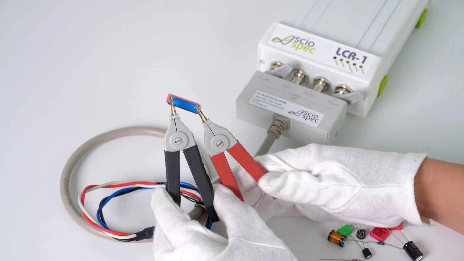
In general, LCR meters work on similar principles as impedance analyzers and the same parameters are to be considered. When measuring electrical impedance, key specifications include frequency and impedance measurement ranges, accuracy, speed and sweep point count. Just as important are requirements of the test setup´s connection topology (2-terminal or 4-terminal Kelvin), bias control, and system scalability – when it comes to multichannel or high throughput problems. Since most applications require special care contacting a “device under test” the interface and extension possibilities of the instruments are also to be considered. High-accuracy LCR measurements typically rely on four-terminal Kelvin connections, which eliminate errors caused by test lead resistance and contact impedance.
Modern LCR instruments typically include programmable test frequencies, selectable signal levels, Kelvin connections for precision measurements, and remote interfaces for automation. These capabilities allow the instrument to be integrated into laboratory setups as well as automated production test systems. Many benchtop LCR meters also allow a DC bias voltage or current to be superimposed on the AC measurement signal in order to characterize components under realistic operating conditions.
Looking at instruments for impedance spectroscopy it is essential to look deeper than just the plain key specification from a product summary. Accuracy and speed both are at least dependent on frequency and absolute value of the measured impedance. Most manufacturers will specify across a very large range of impedances and frequencies, but a closer look into the datasheet will reveal that only certain ranges are covered in full accuracy. The distribution of these regions varies significantly across instruments. Thus, it is important to look at the accuracy-contour plots (see example below) showing which accuracy can be obtained at what absolute value and frequency. For a detailed comparison of specifications for the most widely used impedance analyzers on the market, check out this article. In simplified terms, LCR meters oftentimes are characterized not in terms of impedance ranges, but in terms of L, C and R ranges. For example, the Sciospec LCR-1 works for R = 1 mΩ … 1 TΩ, C = 10 fF … 1 kF, and L = 1 nH … 1 TH. However, in most cases it is important to measure at a specific test frequency and for that purpose the accuracy contour plots are the best option to understand an instrument’s capabilities. Notice how some of these include scales for inductance and capacitance values for easier readability.
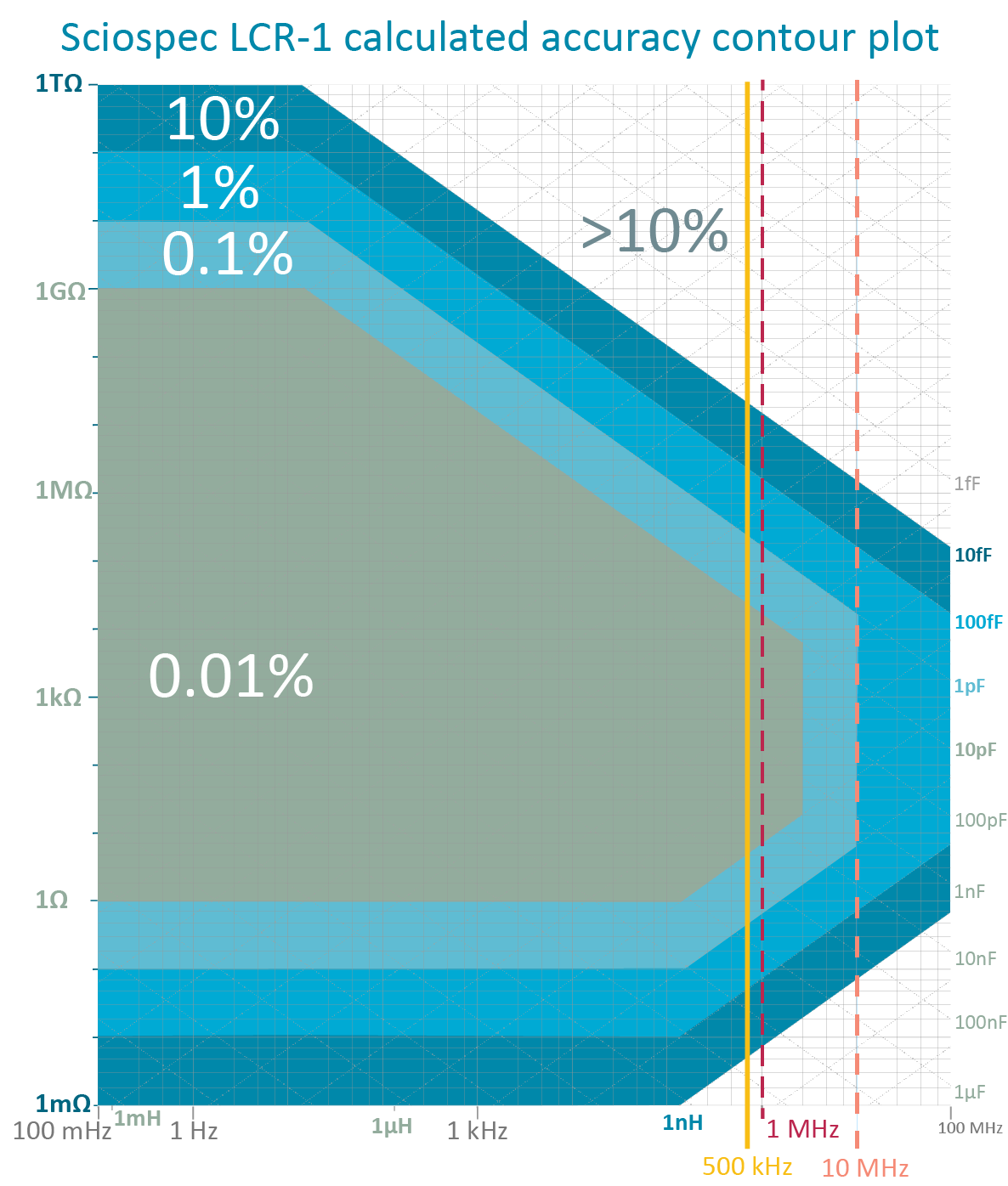
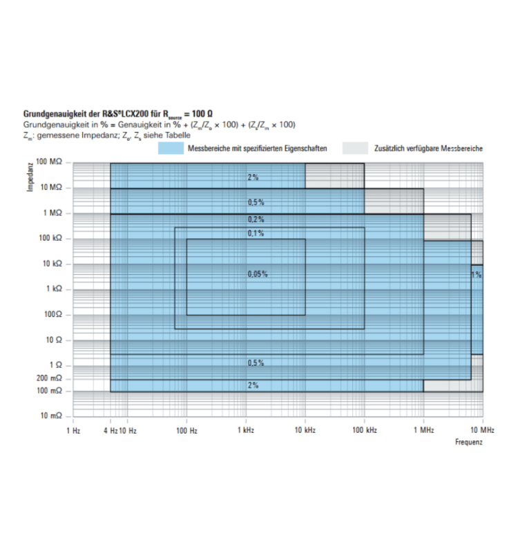
example accuracy contour plots left: Rohde & SchwarzLCX100/200 [source: LCX100/200 datasheet] – logarithmic axis ranging from 4 Hz to 10 MHz and 100 mΩ to 100 MΩ, right: Sciospec LCR-1 [source Sciospec LCR-1 datasheet] – logarithmic axis ranging from 100 µHz to 100 MHz and 1 mΩ to 1 TΩ,
The right LCR meter for every need – Sciospec´s product range
For all component testing scenarios, the Sciospec LCR-1 packs just the right features. Based on the same technology as our proven impedance analyzers the LCR-1 combines the measurement performance of high-end impedance analyzers with the simplicity expected from an LCR instrument. In terms of range, accuracy and speed the LCR-1 offers performance comparable to high-end instruments while maintaining a compact formfactor, simple setup and ease of use previously unseen in this class. Ranging from 1 mΩ … 1 TΩ, 10 fF … 1 kF, 1 nH … 1 TH the LCR-1 is specified for 0.01% base accuracy and an impedance range only challenged by top of the line impedance analyzers. The large selection of compatible test adapters enables all commonly seen component and material test scenarios and the modern, easy to use software user interface makes testing straightforward and accesible.
For more advanced capabilities and even more options you can also consider our impedance analyzer product range. Selecting the appropriate instrument class is critical:
Looking to Embed High Accuracy LCR Measurement into Your Product?
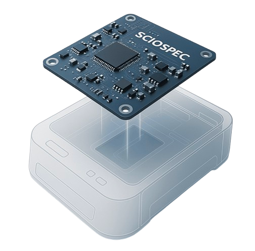
Integrating LCR measurement capabilities into complex setups and products takes time and resources. Don’t let this slow your innovation or inflate your R&D budget. Sciospec`s proven measurement technology allows your team to seamlessly embed ready-to-integrate measurement solutions directly into your system. We handle the measurement complexity so you can focus on your unique value proposition.
Tailored to Your Needs: Whether you require higher channel counts, specialized connectivity, custom form factors, or seamless integration into automated test setups – we provide the adaptability to make it work for you.
Leverage our validated LCR technology to significantly shorten your design cycle and get your product to market faster, instead of developing sensitive analog hardware from the ground up.
Ready to streamline your product development? Contact us today to discuss your specific OEM requirements, or visit our OEM solutions page for more information on integrating Sciospec LCR technology.
Frequently Asked Questions
An LCR meter is a specialized electrical test instrument used to measure the fundamental parameters of passive components: inductance (L), capacitance (C), and resistance (R). Professional instruments apply a sinusoidal AC excitation signal to a device under test (DUT) to calculate impedance (Z), phase angle, and various derived parameters such as the dissipation factor (D), quality factor (Q), and equivalent series resistance (ESR). These measurements are essential for characterizing component behavior under realistic AC operating conditions rather than simple DC states.
They are widely used in laboratories, production environments, and quality control because they provide high accuracy and repeatability for electrical parameter measurements.
These instruments are available as handheld LCR meters for portable use, as well as benchtop systems for higher stability, extended frequency range, and automation.
Most LCR meters operate by exciting the component with a known test frequency and voltage, then measuring the magnitude and phase relationship between current and voltage. From these measurements, the instrument derives inductance, capacitance, and resistance, which are commonly referred to as the primary parameters of the component. Depending on configuration, additional parameters such as impedance magnitude or phase angle may also be displayed.
The key difference between an LCR meter and a multimeter lies in how measurements are performed and what parameters are resolved.
A multimeter typically measures resistance using a DC signal and may provide basic capacitance measurement based on charge-discharge timing. This approach is sufficient for rough checks but does not represent real operating conditions for most components. Multimeters do not allow control over test frequency, signal level, or phase behavior.
An LCR meter, by contrast, applies an AC signal at one or more selectable test frequencies. This allows the meter to evaluate how a component behaves under realistic electrical excitation. Because inductance and capacitance are inherently frequency-dependent, this distinction is critical for accurate results.
Additionally, LCR meters can measure phase angle, impedance, and related parameters that a multimeter cannot resolve. For in-circuit testing or component verification in production, most LCR meters offer significantly better accuracy, resolution, and control than a general-purpose multimeter.
In short, multimeters are general diagnostic tools, while LCR meters are specialized instruments optimized for precise component measurements.
The choice depends on whether the application requires broadband spectroscopy or discrete-frequency component characterization. You should utilize an LCR meter for high-throughput production testing, incoming quality control, and R&D scenarios where measurements at specific, standard test frequencies are sufficient. An impedance analyzer is necessary for advanced research involving wideband frequency sweeps, complex equivalent circuit modeling (e.g., Nyquist or Bode plots), and identifying unknown resonances in materials or electrochemical systems.
Selecting the appropriate instrument depends on your specific DUT requirements, particularly the required test frequency range, basic measurement accuracy, and test signal levels (voltage and current). Critical operational factors include measurement speed—especially for automated production—and the availability of 4-terminal Kelvin connections to eliminate lead resistance errors. For industrial or research environments, the support for remote interfaces (SCPI/API) and the availability of specialized test fixtures for different component geometries are also primary considerations.
Series and parallel modes refer to the equivalent circuit models the instrument uses to interpret the measured impedance. The optimal choice depends on the impedance of the DUT: the series model is generally used for low-impedance components (like large capacitors or small inductors) where lead resistance dominates losses, while the parallel model is used for high-impedance components (like small capacitors or large inductors) where leakage resistance is the primary loss factor. Selecting the correct mode is vital for the accurate derivation of L, C, and R values from the raw impedance data.
These parameters define the efficiency and loss characteristics of a component. Equivalent Series Resistance (ESR) represents all internal resistive losses in a capacitor or inductor, which is critical for power applications. The dissipation factor (D) and tan delta measure the ratio of energy dissipated to energy stored, while the quality factor (Q) is the inverse of D, indicating the efficiency of an inductor. These values are frequency-dependent and provide deeper insight into component reliability and heat generation than nominal L or C values alone.
Calibration intervals depend on your internal quality management system, the stability of your environment, and specific regulatory requirements, though an annual interval is common in professional labs. Accreditation to ISO/IEC 17025 is the global standard for calibration competence, ensuring traceability to national standards. In specific regions or industries, standards such as ANSI/NCSL Z540.1 may also apply to define calibration documentation and uncertainty budgets.
Measurement results vary because real-world components exhibit frequency-dependent behavior due to parasitics, material properties, and core saturation in inductors. The signal level (test voltage or current) can also influence results, particularly in non-linear components or materials where higher signal levels might induce self-heating or shift the operating point. It is essential to characterize components at frequencies and levels that match their intended application to ensure the data is representative of real-world performance.
In production, LCR meters are used for high-speed incoming inspection of passive components, automated pass/fail testing, and binning based on specified tolerances. They are often integrated into automated test equipment (ATE) to verify PCB assembly integrity or to qualify the performance of sensors and filters before final product integration. This ensures that only components meeting strict electrical parameters enter the supply chain, reducing manufacturing defects and improving long-term reliability.
Yes, professional LCR meters are designed for seamless integration via remote interfaces such as LAN, USB, or GPIB using standardized SCPI command sets. Integration success depends on the instrument’s support for hardware triggers, fast measurement speeds, and the ability to handle data logging and automated binning sequences. For OEM applications, modular “engines” can be embedded directly into larger systems to provide on-board LCR measurement for sensor readout or self-diagnostics.
A 2-wire setup is sufficient for high-impedance DUTs where lead resistance is negligible. A 4-terminal Kelvin connection is mandatory for low-impedance measurements to eliminate the effects of test lead and contact resistance, which can otherwise introduce significant errors. Guarding is an additional technique used to eliminate the effects of stray capacitance and leakage paths to ground, ensuring that only the current flowing through the DUT is measured.
Handheld meters offer portability for field service and quick diagnostics but typically sacrifice frequency range, test signal flexibility, and absolute accuracy compared to benchtop models. Benchtop instruments provide higher stability, more advanced automation interfaces, and the precision required for rigorous R&D or high-volume production characterization. The choice depends on whether the priority is convenience and mobility or traceable precision and laboratory-grade performance.
LCR meters are highly effective for characterizing materials and sensors by measuring capacitance and tan delta (dielectric loss) as a function of environmental changes or frequency. They are frequently used in research for polymers, composites, and MEMS devices to track performance and material aging. Whether an LCR meter is sufficient depends on if the required frequencies are within its selectable range and if the material’s response is relatively linear within the test signal levels provided.
Instrumentation must comply with IEC 61010 safety categories, which define the protection level against voltage transients in different electrical environments (e.g., CAT I for lab vs. higher categories for mains-connected industrial floors). Compliance also involves adhering to voltage and current limits to prevent DUT damage and ensuring that all calibration documentation meets industry-specific quality standards. The operational environment—including temperature, humidity, and electromagnetic interference—should be controlled to ensure measurements remain within the instrument’s specified accuracy limits.
Open and short compensation is a critical procedure used to remove the residual impedance of test leads and fixtures from the final measurement results. To perform this, you first execute an “Open” measurement with the terminals disconnected to characterize stray capacitance and conductance, followed by a “Short” measurement with a zero-impedance shorting bar to characterize residual resistance and inductance. Modern digital LCR meters then mathematically subtract these parasitic values from the device under test (DUT) measurement. Failing to perform this compensation, especially at high frequencies or when measuring very low impedance, will result in significant measurement offsets and invalid data.
Applying a DC bias (either voltage or current) allows you to characterize how a component performs under real-world operating conditions, such as a capacitor in a power supply rail or an inductor in a DC-DC converter. For inductors, a DC current bias can reveal the saturation point where inductance begins to drop, while for certain capacitors (like MLCCs), a DC voltage bias can significantly reduce the effective capacitance. Instruments must be designed to handle these bias levels without damaging the internal sensing circuitry, often requiring specialized internal or external bias sources to maintain measurement stability.
In precision LCR measurement, there is an inherent trade-off between the time taken for a measurement and the quality of the data; increasing the integration time or averaging reduces noise and improves resolution and accuracy. For high-speed production testing, you must prioritize speed to maintain throughput, which may require accepting a wider uncertainty budget. Conversely, R&D characterization typically prioritizes high resolution and low uncertainty at the expense of measurement time. Understanding this relationship is essential for selecting the correct measurement settings for your specific application requirements.
A list sweep allows the LCR meter to measure at a series of predefined, discrete frequency points or test levels, which is highly efficient for automated production testing where only specific operating points are relevant. In contrast, a continuous frequency sweep—more common in impedance analyzers—provides a broadband view across a range, which is necessary for identifying unknown resonances or characterizing material transitions. While advanced LCR meters like the LCR-1 support list sweeps to simulate frequency-dependent behavior, they are optimized for discrete point precision rather than the broad spectral analysis of a full impedance analyzer.
A total uncertainty budget involves more than the instrument’s base accuracy; it must account for test frequency, signal levels, fixture parasitics, and environmental factors such as temperature and humidity. You must combine the instrument’s specified accuracy at the specific operating point (derived from accuracy-contour plots) with the uncertainties introduced by lead compensation, contact resistance, and calibration traceability. This rigorous approach is a mandatory requirement for maintaining compliance with ISO/IEC 17025 and ensures that measurement results are comparable across different laboratories and distributed production sites.
The accuracy of an LCR meter depends on the instrument class, frequency range, test conditions, and measurement setup. High-quality digital LCR meters are designed to deliver high accuracy across defined impedance and frequency ranges when used within their specified limits.
Several factors influence measurement accuracy:
- Test frequency: Component behavior varies with frequency, and accuracy is highest when the selected frequency matches the intended application.
- Signal voltage: Excessive voltage can introduce non-linear effects, while insufficient voltage may reduce signal-to-noise ratio.
- Calibration: Proper calibration compensates for internal offsets and fixture effects.
- Connection method: Using appropriate probes, sockets, or four-terminal connections reduces lead and contact resistance error.
- Measurement speed and filters: Averaging and filtering improve accuracy at the expense of speed.
Most LCR meters are optimized for passive component testing under stable conditions. When operated within specification, they provide reliable, repeatable measurements suitable for laboratories, development, and production environments.
It is important to note that accuracy is not uniform across the entire range. Each instrument has defined limits where measurements remain valid, and results outside those limits may be affected by increased error.
To measure inductance using an LCR meter, the inductor is connected to the meter using appropriate probes or terminals, ensuring a stable and repeatable connection. The meter applies an AC signal at a defined test frequency and measures the resulting voltage and current response.
From this response, the instrument calculates inductance based on the measured impedance and phase information. The user typically selects the desired parameter display mode so that inductance is shown directly as the primary value.
Several practical considerations affect inductance measurement:
- Frequency selection: Inductance values can vary with frequency due to core material and parasitic effects. Using programmable frequencies allows characterization under relevant conditions.
- Signal level: Excessive voltage may drive magnetic cores into saturation, affecting accuracy.
- Connection method: Short leads and proper fixture compensation reduce measurement error.
- In-circuit effects: Measuring inductance in circuit may introduce parallel or series paths that influence results.
By controlling frequency, signal level, and measurement configuration, an LCR meter provides accurate and repeatable inductance measurements suitable for both development and production testing.
Who we are working with and for


Relevant publications


Get in touch with us

+49 3425 88399 00

info@sciospec.de

Sciospec Scientific Instruments GmbH
Leipziger Str. 43b, 04828 Bennewitz, Germany
